SEPTA A/B SLC-500 PLC HYD
2000 CODE COMPLIANT HYDRUALIC ELEVATOR CONTROLLER
OPERATION MANUAL
CONVENTIONS
This manual uses the following terms and conventions to indicate parts of the controller and operation:
- CPU/PLC – The electronic controller board and all of it's associated expansion boards.
- Energized – Power is applied to the relay coil, and the relay has operated.
- De-energized – Power is not applied to the relay coil, and the relay is at rest.
- Activated – A signal is applied to the input terminal on the CPU or CPU expansion board.
- De-activated – A signal is not applied to the input terminal on the CPU or CPU expansion board.
- Symbol – a letter or letter number code referring to a relay or terminal. Example: PX
- Symbol number/number – A contact pair on a relay Example: PX 1/7
- Symbol – An input / output on the CPU board. Example: A(1)
- Symbol – An input / output on an expansion board. The first number indicates which I/O board, the second indicates the terminal. Example: 1C(1-13)
- #symbol – A terminal on the connection terminal strip. Example: #OF1
- #symbol to #symbol – Indicates an external electrical connection between two terminals. Example: #27 to #28
LEGEND
Table 1 outlines the symbols used in the ESI Drawings. Please refer to this table whenever you have any questions regarding symbols on the ESI Drawings.
| Symbol | Symbol Name | Notes |
|---|---|---|
| Fuse | Top Number represents the fuse number. Bottom Number represents the Amperage. | |
| Terminal | The Lettering (beginning with#) represents the terminal name. | |
| Normally Open Contact (Contactor) | The Lettering represents the Contactor Name (i.e. P) and the Number represents the Contact Number (i.e. 1) | |
| Normally Closed Contact (Contactor) | The Lettering represents the Contactor Name (i.e. P) and the Number represents the Contact Number (i.e. 6) | |
| Normally Open Contact (Relay) | The Lettering represents the Relay Name (i.e. Z) and the Numbers represents the Relay Terminals (i.e. 1 and 7) | |
| Normally Closed Contact (Relay) | The Lettering represents the Relay Name (i.e. I) and the Numbers represents the Relay Terminals (i.e. 5 and 8) | |
| Relay Coil | The Lettering represents the Relay Name (i.e. TC). The small circle to the right of the Relay represents the Right Terminal of the Coil. | |
| Resistor | The Lettering represents the resistor value (i.e. 15kΏ) | |
| Capacitor | The Lettering represents the capacitance value (i.e. 40µF) | |
| Diode | ||
 |
Switch | The Lettering represents the name of the switch (i.e. BOT FINAL). NOTE: Switch shown in Closed Position. |
| Region | This symbol is used to refer to a different area on the drawing (i.e. Area Labeled H) | |
| Resistor | The Lettering represents the resistor value (i.e. 150Ώ) | |
| Resistor (Tapped) | The Lettering represents the resistor value (i.e. 250Ώ) | |
| Switch | The Lettering represents the name of the switch (i.e. PIT SWITCH). NOTE: Switch shown in Closed Position. | |
| Switch | The Lettering represents the name of the switch (i.e. GOVERNOR SWITCH). NOTE: Switch shown in Closed Position. | |
 |
Transformer | The Lettering on the Left Side represents the Primary Voltage (i.e. 208VAC) and the Lettering on the Right Side represents the Secondary Voltage (i.e. 120VAC). |
| Switch | The Lettering represents the name of the switch (i.e. FX). NOTE: Switch shown in Open Position. | |
 |
CPU Inputs | The Lettering represents the Input name (i.e. SW, GS, and DLK). The Numbers represent the Input location. (i.e. SW = IN 5, GS = IN 6, DLK = IN 7). |
| CPU Inputs | The Lettering represents the Input name (i.e. 38 | |
 |
CPU Outputs | The Numbers represent the Output Number on the CPU (i.e. Drawing is showing Outputs 18 and 19). |
 |
Dry Contact Outputs | The Lettering represents the Dry Contact Output name. The Number represents the Output Number (i.e. Dry Contact Output URP, Output number 2). |
 |
Key Switch | The Lettering represent the Switch Name (i.e. IN CAR FIREMAN KEY SW) and the Pole Names (i.e. OFF, ON and HOLD). Three position key switch pictured. |
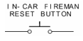 |
Push Button | The Lettering represents the Button Name (i.e. IN CAR FIREMAN RESET BUTTON). |
| Overload | Current Sensing Portion of the Overload Protection. | |
| Light | The Lettering represents the name of the Light (i.e. UP). | |
 |
Buzzer | The Lettering represents the name of the Buzzer (i.e. Door Delay Buzzer). |
| Hall Lantern | ||
| Board Connector | The Lettering represents the connector name (i.e. J1). The number represents the Pin (i.e. 5). | |
| Variable Timer Delay | ||
 |
Switch | The Lettering represents the name of the switch (i.e. IN CAR STOP SWITCH). NOTE: Switch shown in Closed Position. |
CONTROLLER LAYOUT

CONTROLLER COMPONENT OVERVIEW
The controller is designed for maximum reliability with minimum maintenance. An Allen Bradley SLC-503 PLC coupled with a series of forced guided relays provides all the functionality to run the elevator. The PLC unit provides the control logic. The safety circuits are controlled by both the PLC and relay structure for maximum reliability and redundancy in all modes of operation. A Siemens soft starter controls the pump motor and provides motor overload and fault protection. All relays have an internal indicator light (a board mounted LED for board mounted relays) that illuminates when power is provided to the relay coil. This allows the status of all relays to be verified quickly. In addition, the PLC input and output modules have indicator lights for each input and output. Also, there is an on board user interface with a six inch touchscreen.
A reverse phase relay on the board provides reverse phase protection to the controller. An optional Uninterruptible Power Supply (UPS) can provide ‘backup’ power to lower the elevator in case of a power or phase failure.
Every controller has three toggle switches. These are: test mode, hall button disconnect and automatic/inspection. There are also three push button inputs on every controller. They are controller inspection down, enable and up. There are also two slide switches: Car Door Bypass and Hatch Door Bypass. A vertical terminal strip provides all interconnecting to the elevator’s equipment.
The relays, Inputs and Outputs names and functions are described in the following tables:
Relay Names:
| RELAY NAME | FUNCTION | TYPE | LOCATION |
|---|---|---|---|
| D | Run Down | 6 Pole Safety | BRD_DRV_H |
| HSP | High speed Pilot | 2 Pole Safety | BRD_DRV_H |
| HS | High speed | 2 Pole Safety | BRD_DRV_H |
| HSX | High speed | 2 Pole Safety | BRD_DRV_H |
| HSY | High speed | 2 Pole Safety | BRD_DRV_H |
| HSZ | High speed | 2 Pole Safety | BRD_DRV_H |
| JS | Jack Synchronization | 2 Pole Safety | BRD_DRV_H |
| PF | Phase protection | KUP | BRD_DRV_H |
| PX | Running | 2 Pole Safety | BRD_DRV_H |
| PY | Running | 2 Pole Safety | BRD_DRV_H |
| R | Run Pump | 2 Pole Safety | BRD_DRV_H |
| U | Run Up | 2 Pole Safety | BRD_DRV_H |
| RELAY NAME | FUNCTION | TYPE | LOCATION |
|---|---|---|---|
| I | Inspection – energized on automatic | 2 Pole Safety | RB Board |
| IX | Inspection Aux | 2 Pole Safety | RB Board |
| IC1 | In car inspection – energized on automatic | 2 Pole Safety | RB Board |
| IC2 | In car inspection – energized on | 2 Pole Safety | RB Board |
| ID | Inspection Down | 2 Pole Safety | RB Board |
| IU | Inspection Up | 2 Pole Safety | RB Board |
| LFI | Lobby Fire Independent | 2 Pole Safety | RB Board |
| CT | Cycle Test | 2 Pole Safety | RB Board |
| SWB | Stop switch bypass | 2 Pole Safety | RB Board |
| SWB2 | Stop switch bypass | 2 Pole Safety | RB Board |
| RELAY NAME | FUNCTION | TYPE | LOCATION |
|---|---|---|---|
| DL | Door Locks | 2 Pole Safety | Door Board |
| GS | Gate Switch | 2 Pole Safety | Door Board |
| VC | Leveling | 2 Pole Safety | Door Board |
| Z | Door Zone | 2 Pole Safety | Door Board |
| RELAY NAME | FUNCTION | TYPE | LOCATION |
|---|---|---|---|
| ACC | Access | 6 Pole Safety | Access Board |
| ACX | Access Aux. Relay | 6 Pole Safety | Access Board |
| BAC | Access Bottom Control | 6 Pole Safety | Access Board |
| TAC | Access Top Control | 6 Pole Safety | Access Board |
| RELAY NAME | FUNCTION | TYPE | LOCATION |
|---|---|---|---|
| C, O , NR | Front Door Contactors | GMC-12 | Panel Mtd |
| CR, OR , NRR | Rear Door Contactors | GMC-12 | Panel Mtd |
| BU, TD | Access Limit relays | KUP | Access Board |
SYSTEM INPUTS
| INPUT | Symbol | FUNCTION |
| 1-0 | ON | 120 VAC power on |
| 1-1 | TC | Top Car Inspection (when de-activated) |
| 1-2 | IC | In Car Inspection (when de-activated) |
| 1-3 | ACC | Access |
| 1-4 | I | Controller Inspection (when de-activated) |
| 1-5 | ID | Inspection Down |
| 1-6 | IU | Inspection Up |
| 1-7 | SAF | All Safeties Closed |
| 1-8 | SW | Stop Switch Closed |
| 1-9 | GS | Gate Switch |
| 1-10 | DL | Hatch Door Lock |
| 1-11 | DRV | Doors/Gate/Inspection |
| 1-12 | 37 | Bot Normal Limit |
| 1-13 | 38 | Top Normal Limit |
| 1-14 | !PF | Power Failure (when activated) |
| 1-15 | FLT | Soft Start Fault |
SYSTEM INPUTS
| INPUT | Symbol | FUNCTION |
| 2-0 | P1 | Proving Input 1 |
| 2-1 | P2 | Proving Input 2 |
| 2-2 | P3 | Proving Input 3 |
| 2-3 | TST | Test Switch Input |
| 2-4 | GB | Car Door Bypass |
| 2-5 | DBY | Hoistway Door Bypass |
| 2-6 | 52 | Bottom Slowdown Limit |
| 2-7 | 53 | Top Slowdown Limit |
| 2-8 | 81 | Down Level Unit |
| 2-9 | 82 | Up Level Unit |
| 2-10 | 84 | Door Zone |
| 2-11 | 85 | 2nd Floor Zone Switch Inputs |
| 2-12 | ||
| 2-13 | ||
| 2-14 | ||
| 2-15 | TOL | Thermal Overload Limit |
SYSTEM INPUTS
| INPUT | Symbol | FUNCTION |
| 3-0 | 24 | Door Close Button |
| 3-1 | 28 | Door Open Button |
| 3-2 | 28E | Door Electric Eye |
| 3-3 | 47 | Door Close Limit |
| 3-4 | 48 | Door Open Limit |
| 3-5 | 50 | Independent Service Key Switch |
| 3-6 | 90 | Smoke / Heat Detectors (Alternate Return) |
| 3-7 | 90B | Machine Room Smoke / Heat Detectors (Alternate Return) |
| 3-8 | 92 | Smoke / Heat Detectors (Prime Return) |
| 3-9 | 92B | Machine Room Sensors / Heat Detectors (Prime Return) |
| 3-10 | 93 | Fire Control Lobby Switch (BYPASS) |
| 3-11 | 94 | Fire Control Lobby Switch (ON) |
| 3-12 | 95 | Fire Control InCar Switch (ON) |
| 3-13 | 96 | Fire Control InCar Switch (RESET) |
| 3-14 | 99 | Fire Control InCar Switch (HOLD) |
| 3-15 | 100 | Fire Control InCar Switch (OFF) |
SYSTEM INPUTS
| INPUT | Symbol | FUNCTION |
| 4-0 | 24R | Rear Door Close Button |
| 4-1 | 28R | Rear Door Open Button |
| 4-2 | 28ER | Rear Door Electric Eye |
| 4-3 | 47R | Rear Door Close Limit |
| 4-4 | 48R | Rear Door Open Limit |
| 4-5 | ||
| 4-6 | ||
| 4-7 | ||
| 4-8 | 51 | Mode SW |
| 4-9 | 64 | Release Button in Cashier Station |
| 4-10 | ||
| 4-11 | ||
| 4-12 | ||
| 4-13 | ||
| 4-14 | ||
| 4-15 | X1 | AUTO / CASHIER Release |
SYSTEM INPUTS
| OUTPUT | Symbol | FUNCTION |
| 5-0 | CT | Cycle Test |
| 5-1 | PP | Run Pilot |
| 5-2 | DP | Down Run |
| 5-3 | UP | Up Run |
| 5-4 | RP | Up Pump |
| 5-5 | HSP | High Speed Pilot |
| 5-6 | VCP | Leveling Pilot |
| 5-7 |
SYSTEM INPUTS
| OUTPUT | Symbol | FUNCTION |
| 6-0 | SWB | Stop Switch Bypass Pilot |
| 6-1 | JS | Jack Synchronization |
| 6-2 | OX | Door Open Pilot |
| 6-3 | CX | Door Close Pilot |
| 6-4 | NRX | Nudging Pilot |
| 6-5 | OXR | REAR Door Open Pilot |
| 6-6 | CXR | REAR Door Close Pilot |
| 6-7 | NRRX | REAR Nudging Pilot |
| 6-8 | 21 | Down Directional Light |
| 6-9 | 23 | Up Directional Light |
| 6-10 | 61 | Stop / Pass Gong |
| 6-12 | 97 | Fire Control Light |
| 6-13 | 97B | Fire Buzzer |
| 6-14 | 97L | LOBBY Fire Light |
| 6-15 |
SYSTEM INPUTS
| INPUT | Symbol | FUNCTION |
| 7-0 | 1C | First Floor Car Call |
| 7-1 | 2C | Second Floor Car Call |
| 7-2 | 3C | Third Floor Car Call |
| 7-3 | 29 | Door Quick Close Button |
| 7-4 | ||
| 7-5 | ||
| 7-6 | ||
| 7-7 | ||
| 7-8 | 1H | First Floor Hall Call |
| 7-9 | 2D | Second Floor Down Hall Call |
| 7-10 | 2UR | Second Floor Up Hall Call |
| 7-11 | 3H | Third Floor Hall Call |
| 7-12 | ||
| 7-13 | ||
| 7-14 | ||
| 7-15 |
SYSTEM INPUTS
| OUTPUT | Symbol | FUNCTION |
| 8-0 | 1A | First Floor Car Call Acknowledge |
| 8-1 | 2A | Second Floor Car Call Acknowledge |
| 8-2 | 3A | Third Floor Car Call Acknowledge |
| 8-3 | ||
| 8-4 | ||
| 8-5 | ||
| 8-6 | ||
| 8-7 | ||
| 8-8 | 1HA | First Floor Hall Call Acknowledge |
| 8-9 | 2DA | Second Floor Down Hall Call Acknowledge |
| 8-10 | 2UAR | Second Floor Up Hall Call Acknowledge |
| 8-12 | 3HA | Third Floor Down Hall Call Acknowledge |
| 8-13 | ||
| 8-14 | ||
| 8-15 |
SYSTEM INPUTS
| OUTPUT | Symbol | FUNCTION |
| 9-0 | 1I | First Floor Indicator |
| 9-1 | 2I | Second Floor Indicator |
| 9-2 | 3I | Third Floor Indicator |
| 9-3 | ||
| 9-4 | DG | Front Down Car Travel Lantern |
| 9-5 | UG | Front UP Car Travel Lantern |
| 9-6 | DGR | Rear Down Car Travel Lantern |
| 9-7 | UGR | Rear UP Car Travel Lantern |
| 9-8 | 65 | Cashiers Station Amber Lt |
| 9-9 | 66 | Cashiers Station White Lt |
| 9-10 | 67 | Cashiers Station Buzzer |
| 9-12 | ||
| 9-13 | ||
| 9-14 | ||
| 9-15 |
PRE POWER CHECK OUT
Prior to shipment, the controller is given a series of thorough tests to ensure proper operation. However, it is possible that components could have loosened or been damaged during shipment. Therefore, before applying power, it is a good idea to check the following:
- Check for loose
- Check that no components were bent in
- Make sure all plug in relays are fully inserted and
- Check that all CPU terminal strips fully inserted
- Make sure all toggle switches are in the down
- CONFIRM input power The input power supply specifications are printed near the terminals.
INITIAL POWER TURN ON
Relay PF should be energized. The RPR should be lit. If the RPR is not lit then reverse the wires into #L1 and #L3.
Check that voltage across terminals #L1 and #L2. Verify that the voltage reading is 208VAC. The voltage across the Primary side of the control transformer should be 208VAC and the voltage across the Secondary side of the transformer should be 120VAC.
The Secondary side of the transformer ties into the RB board where power is routed to different parts of the controller. Verify the following terminal pairs have 120VAC present:
- #27 – #60
- #31 – #60
- #91 – #60
- #32 – #60 – (With CT Relay IN )
- #30 – #60 – (Hall Button Switch Closed)
If all voltages are within range and all safety circuits are properly wired, running the car on Top of Car Inspection should be done first. See the sequence of operation for a full description of this procedure.
SEQUENCE OF OPERATION
Before we can run the controller the safety mechanisms must all be in place. Verify that the following safety circuits are closed.
- #32A to #33 – Final Limits, Pit Switch
- #40 to #41 – Escape Hatch, Top of Car Stop Switch
- #41 to #42 – In/Car Stop Switch
- #42 to #45 – Car Door Contacts
- #34 to #34A – Bottom Hatch Door Interlock
- #34A to #34D – Inter Flr Hatch Door Interlocks
- #34D to #35 – Top Hatch Door Interlock
- #37 to #39 – Bottom Normal Limit
- #38 to #39 – Top Normal Limit
TOP OF CAR INSPECTION
Relay that must be energized: PF
Relays that must be de-energized: ACC, ACX, I, IX, IC1, and IC2. Input TC should be off.
Note: Relays can be verified by looking for an illuminated lamp inside the relay case or LED for board mounted relays.
In order to move the car on Top of Car Inspection, constant pressure must be applied to the buttons. The buttons will allow voltage to flow from terminals #TI to #IU or #TI to #ID. The car will move up and down by energizing the IU or ID relay and input.
Caution: Ensure that all personal working on the elevator understand that the car will be moving during this procedure.
Top of Car Inspection UP RUN
Pressing the Top of Car UP RUN and Safety button (#TI to #IU) will send a signal to the controller (via input [1-6] -IU) that up motion is requested. Relay IU will pick and feed voltage to input DRV via a NO contact. The CPU will fire an output (output [5-3] -UP) energizing relay
U. Relay PX is controlled via another output (output [5-1] -PP) and a normally open (NO) contact from U or D. The CPU will fire another output(s) (output [6-3] –CX, [6-6] -CXR) that will force the doors closed. The motor starter and up slow speed valve will be energized and the car will run up at slow speed (once the motor is up to speed). The CPU display will read ‘Up Slow Speed’. Releasing the switch will stop the car immediately.
Top of Car Inspection DOWN RUN
Pressing the Top of Car DOWN RUN and Safety button (#TI to #ID) will send a signal to the controller (via input [1-5] -ID) that down motion is requested. Relay ID will pick and feed voltage to input DRV via a NO contact. The CPU will fire an output (output [5-2] -DP) energizing the D and DX relays. Relay PX is controlled via another output (output [5-1] -PP) and a NO contact from U or D. The CPU will fire another output(s) (output [6-3] –CX, [6-6] -CXR) that will force the doors closed. The down slow speed valve will be activated and the car will run down. The display will read ‘down slow speed’. The motor will not start.
IN CAR INSPECTION
Relay that must be energized: PF, IC1, IC2.
Relays that must be de-energized: ACC, ACX, I, and IX. Input IC should be off.
Note: Relays can be verified by looking for an illuminated lamp inside the relay case or LED for board mounted relays.
In order to move the car on In Car Inspection, constant pressure must be applied to the buttons. The buttons in the car station are used to control the car while on In Car Inspection. Voltage flow is controlled from #IC1 to #ICU (in order to run up) or from #IC1 to #ICD (in order to run down). The car will move up and down by energizing the IU or ID relay and input. The feed to relays IU and ID are also interrupted by NO contacts from IC1 and IC2 so these relays must be on to move while on In Car Inspection.
Caution: Ensure that all personal working on the elevator understand that the car will be moving during this procedure.
ACCESS
Relay that must be energized: PF, ACC, ACX.
Relays that must be de-energized: I, IX, IC1, and IC2. Input ACC should be on.
Note: Relays can be verified by looking for an illuminated lamp inside the relay case or LED for board mounted relays.
In order to move the car on Access, constant pressure must be applied to the key switches. The key switches will allow voltage to flow from terminals #AC to either #ACU or #ACD depending on whether Access Up or Access Down direction is being selected. There are two other relays associated with Access. They are TAC and BAC. The TAC is enabled when the Access Key Switch on the top of the hoist way is selected. The BAC is enabled when the Access Key Switch on the bottom of the hoist way is selected. The car will move up and down by energizing the IU or ID relay and input.
The Hatch Door Interlock at the bottom floor is bypassed via NO contacts from the ACX relay and BAC relay. The Hatch Door Interlock at the top floor is bypassed via NO contacts from the ACX relay and TAC relay. The Gate Switch is bypassed via NO contacts from the ACC relay and either TAC or BAC relays.
Caution: Ensure that all personal working on the elevator understand that the car will be moving during this procedure.
CONTROLLER INSPECTION
With the top of car and access switches closed, the controller can be run via the controller inspection switch. Care should be exercised to ensure that personnel are clear of the car, and that the car does not run past the final limits.
AUTOMATIC OPERATION
Relays that must be energized: I, IX, PF.
Inputs that must be activated:
ON,TC, IC, I, SW, GS, DL, SAF, SW
Inputs that must NOT be activated: 50, 68
Set controller inspection switch to “Automatic”, be sure top-of-car inspection and in-car inspection switches are closed.
When the controller is in automatic mode, the display will read “Automatic”. If you do not see the word ‘Automatic’ on the display, the elevator is not in automatic mode. Automatic is the normal mode of operation for the elevator when it is in service.
Automatic UP RUN
With the car level at the first floor, inputs “84” [2-10] Door Zone, “53” [2-7] Top SlowDown and output “1I” (9-0) will be ON. Input “52”[2-6] Bottom SlowDown will be OFF. Pressing 2nd floor car button will activate input 2C [7-1] and output 2A (8-1) will acknowledge the call. If the doors are not closed, they will wait for the door timeout timer to expire. In order to cancel the door timeout, the Door Close Button (#27 to #28) can be pressed and the doors will close immediately. When the hatch doors and car door contacts close (#42 to #45, #34 to #35) ,The PLC outputs UP, RP & PP will energize. The motor starter, up slow speed and up high-speed valve will energize and the car will accelerate up. As the car approaches the second floor, floor zone contact input “85”[2-11] will activate causing the zone to change to two. The indicator lights will change from “1I”(9-0) to “2I”(9-1). When this zone change occurs, the car will slow down by de-energizing output HSP. The car will decelerate into the floor. As the car enters the leveling zone, input “82”[2-9] will be activated by the up leveling unit (#27 to #82). Relay Z and input “84”[2-10] will energize via the door zone unit (#27 – #84). When the up leveling unit turns off, “82” will fall out causing outputs UP and PP to de-energize. The up valves will drop out, and the car will stop. RP output will delay out providing a delay to the pump motor to insure a true valve stop. The car call will cancel as soon as the car comes to a full stop. The OX will energize and the doors will open until input “48” [3-4] is de-activated by the operator’s contacts opening.
Automatic DOWN RUN
With the car level at the 2nd floor, inputs “85”[2-11] 2ndFlr Zone Conact, “84” [2-10] Door Zone, “53” [2-7] Top SlowDown, “52”[2-6] Bottom SlowDown and output “2I” (9-1) will be ON. Pressing 1st floor car button will activate input “1C”[7-0] and output 1A (8-0) will acknowledge the call. If the doors are not closed, they will wait for the door timeout timer to expire. In order to cancel the door timeout the Door Close Button (#27 to #28) can be pressed and the doors will close immediately. The CX relay will stay energized even after the door close limit input #47 (input- [3-3]) turns off since the car has direction. When the hatch doors and car door contacts close (#42 to #45, #34 to #35), the PLC outputs DP and PP will energize. The down slow speed and down high-speed valve will energize and the car will accelerate down. As the car enters the first floor, “52”[2-6] Bottom SlowDown will fall out causing the zone to change to one. The indicator lights to change from 2I (9-1) to 1I (9-0). This zone change causes output HSP (output- [5-5]) to de-energize, and the car will decelerate into the floor. As the car enters the leveling zone, input “81”[2-8] will be activated by the down leveling unit (#27 to #81). Relay Z and input “84”[2-10] will energize via the door zone unit (#27 – #84). When the down leveling unit turns off, “81” will fall out causing outputs DP and PP to de-energize. The down valves will drop out, and the car will stop. As the car comes to a full stop it cancels the car call. The OX will energize and the doors will open until input “48 “[3-4] is de-activated by the operator’s contacts opening.
Cycle Test
The Cycle Test is controlled by the controller (output [5-0] -CTP). The CTP output controls the CT relay, whose NO contacts control the voltage feed to the Critical Circuits. The Cycle Test is sequenced on every run. Normally Closed (NC) contacts from relays I, ID, IU, SWB1, SWB2, IC1, IC2, GS, DL, VC, BAC, TAC, ACC, ACX, HSZ, HSY, HSX, HS, R, PY, PX, D, U and JS
are monitored via Proving Inputs P1, P2 and P3. This verifies that all relays are working appropriately.
Direction Preference
Direction preference is indicated by the state of the Car Travel Lantern. The proper lantern DG (output- [9-4]) / DGR (output [9-6])or UG (output- [9-5]) / UGR (output [9-7]) sounds when the doors reach full open. The direction preference is maintained until the doors are fully closed.
Depending on CPU programming, the DG output may activate, deactivate, and then activate again, to achieve a double chime, if the lantern does not have a double chime unit installed. If a double chime unit is installed, the output can be programmed to simply activate once.
Door Operation
Door relays C, O, NR, CR, OR, and NRR control door operation. The door close button (#27 to #24) will close an open door immediately. The door open button (#27 to #28) will open the door. Electric eye #27 to #28E will also immediately open a closing door. If #27 to #28E is kept closed longer than 25 seconds output -[6-10] will be energized and sound the door delay buzzer through terminal #63. After an additional 5 seconds, the door will nudge closed with both C / CR and NR /NRR energized. NR / NRR and C /CX will de-energize when the door(s) are closed. The quick close button #27 to #29 is the second pole of each car button in parallel.
When a car call is made on any floor other than the lobby, this input will cause the doors to close immediately. The computer is programmed to know which floor is the lobby, and will ignore the quick close feature whenever the elevator is on the lobby floor. If the lobby floor ever changes, the computer simply needs to be re programmed to the new lobby floor, and operation of the quick close feature will work on the new lobby floor.
Independent Service
Independent service is initiated by the key switch terminal #50. While on Independent Service all hall calls are disabled and the car responds to only car calls. The doors remain open until a car call is registered. Continuous pressure of a car call button or the door close button will close the doors, if the doors reach full close the car will run to the selected floor. Releasing the button prior to running causes the doors to reopen and remain open.
Thermal Overload Mode
If the thermal overload switch (#TPR1 to #TPR4) is opened, input “TOL” [2-15] will fall out. This will place the controller in Thermal Overload Mode. The elevator will travel to the lobby floor and stop operating until the thermal overload switch closes.
TOUCH SCREEN LAYOUT
The controller has an AllenBradely TS C600 six inch touch screen which is used for displaying and adjusting controller data.
The general screen layout is shown below:

The [MODE] button is used to page to other screens. The list of available pages is :
- ESI Monitor screen
- Job Information screen
- Event Log screen
- Write enable page
- Parameter pages 2 -> Parameter pages 3 -> Parameter pages 4
- Utility screen
MAIN SCREEN

This is the ESI MONITOR screen. This screen displays the status of the car. Pressing the Mode button advances you to the next screen.
JOB INFORMATION SCREEN

This is the Job Information Screen. This screen displays the job information about this job.
Pressing the Home button to return to the ESI MONITOR SCREEN. Pressing the Mode button advances you to the next screen.
EVENT LOG SCREEN
This is the EVENT LOG SCREEN. This screen displays all the events that are logged by the controller.
Pressing the Home button to return to the ESI MONITOR SCREEN. Pressing the UP ARROW button displays the next event on the screen.
Pressing the DOWN ARROW button displays the previous event on the screen.
Pressing the Mode button advances you to the WRITE ENABLE SCREEN.
WRITE ENABLE SCREEN

This is the WRITE ENABLE SCREEN. This screen allows you to change the timer settings on the next screen(s).
Pressing the Home button to return to the ESI MONITOR SCREEN.
Pressing the Mode button advances you to first Parameter Page for viewing only. Pressing ‘PRESS HERE TO ENTER WRITE ENABLE PARAMETER’ to display:

ENTERING ‘000003’ followed by ‘return’ on the keypad allows you to change the values on the next page(s).
PARAMETER SCREEN Page 2

Pressing the Home button to return to the ESI MONITOR SCREEN. Pressing the Mode button advances you to the UTILITIES MENU SCREEN. Pressing Page UP advances to the next parameter page.
Pressing Page Down returns to the previous parameter page.
Use the ▼ ▲ arrow keys next to the parameter you want to change to change that parameter.
PARAMETER SCREEN Page 3

Pressing the Home button to return to the ESI MONITOR SCREEN. Pressing the Mode button advances you to the UTILITIES MENU SCREEN. Pressing Page UP advances to the next parameter page.
Pressing Page Down returns to the previous parameter page.
Use the ▼ ▲ arrow keys next to the parameter you want to change to change that parameter.
PARAMETER SCREEN Page 4

Pressing the Home button to return to the ESI MONITOR SCREEN. Pressing the Mode button advances you to the UTILITIES MENU SCREEN. Pressing Page UP advances to the next parameter page.
Pressing Page Down returns to the previous parameter page.
Use the ▼ ▲ arrow keys next to the parameter you want to change to change that parameter.
UTILITIES MENU

This is the Utilities Menu Screen.
Pressing the Home button to return to the ESI MONITOR SCREEN. Pressing the Mode button to return to the ESI MONITOR SCREEN.
Pressing the LCD CONFIGURATION BUTTON to change LCD settings. Pressing the CLEAR EVENT LOG BUTTON to clear the event log.
FAQ
The operation manual for this controller is available on the Elevator Systems website and in their Downloads/PLC Manuals section alongside other PLC controller documentation.
Yes — both the relays and PLC input/output modules have indicator lights that show status signals, which aids in troubleshooting and maintenance.
Standard control inputs and switches include:
- Test mode
- Hall button disconnect
- Automatic/Inspection mode
- Manual inspection push buttons
- Car Door Bypass and Hatch Door Bypass slide switches
Yes — it includes an on-board user interface with a touchscreen, making it easier to view status and perform diagnostics.
Safety features include:
- Forced-guided relays working in parallel with PLC logic for redundancy.
- Safety circuits monitored by both PLC and relay hardware.
- Reverse phase protection for the pump motor.
- Optional UPS (Uninterruptible Power Supply) to safely lower the car in power loss conditions.
The core of the system is an Allen-Bradley SLC-500 PLC (typically an SLC-503 CPU), which runs the control logic for the elevator and interfaces with input/output modules and safety relays.
It is specifically engineered to control hydraulic elevator systems, managing motion, safety circuits, and operator inputs.
Yes — this controller is 2000 Code Compliant, meeting applicable industry safety and elevator codes.
The SEPTA A/B SLC-500 PLC HYD is a hydraulic elevator controller that uses an Allen-Bradley SLC-500 programmable logic controller (PLC) combined with safety relays and a touchscreen interface to control and monitor hydraulic elevator operation. It’s designed for reliability, redundancy, and ease of maintenance.